
Circuit-Cim: SPICE in C
Published:
Contents
- Intro to SPICE Algorithm (this article)
- Framework and your first circuit!
- More Static Linear Components
- Nonlinear and Diode
- MOSFET
- Time Variance
- Applications
Intro
CircuitCim is my part of the CESS 4840 Embedded Systems final project CircuitSim, an FPGA-accelerated analog circuit simulator. I call this part CircuitCim, or MGSpice :)
CircuitSim is a state-of-art 4840 final project. It perfectly blends software, hardware, and circuits, allowing us to simulate circuits on FPGA logic circuits. It developed from a Gaussian elimination accelerator, to solving circuits with resistors, capacitors, diodes, to modeling MOSFETs, to NOT gates, to NAND gates, to DFF, and culminates in building a 555 chip from scratch, a perfect combo of analog and digital circuitry.
Meanwhile, CircuitSim (and CircuitCim) is far from perfect: a lot of crappy code (we did get rid of all instances of “vga” and “ball”, which is better than 80% of the teams :)), crappy documentation, and some things didn’t entirely work. Nevertheless, I was pretty proud about this project, so did Edwards and his TA team :)
Solving a circuit is not trivial. You’ll need to solve a system of nonlinear multivariable differential equations. CircuitCim approaches and estimates each aspect incrementally.
In this article, I will break down the code design, and you can learn how to write your own SPICE from scratch!
SPICE Algorithm
Nothing can explain this better than just a diagram:
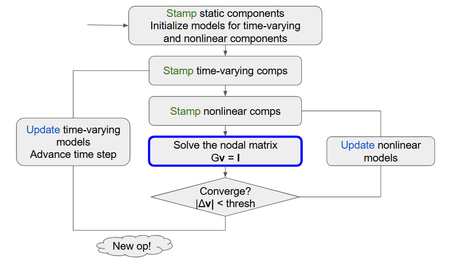
Section 2 will explain “stamp” and “update” in detail.
We don’t have good ways to simulate nonlinear and time-varying components with ODEs– Such ideal behavior only exists in books. The idea behind SPICE is to
- linearize nonlinear components (aka small signal model)
- linearly approximate time-varying components (exponentials are not too hard).
CircuitCim only supports time-domain simulation. The simulation is divided into distinct operating points (op, aka time steps). At each operating point (outer loop), we repeated create linear approximations of nonlinear components until the op converges (inner loop). Then we move to the next op.
As you will see in later sections, every component will be modelled as a combo of independent sources, resistors, and dependent sources. Those can be well-tackled by Node Voltage Analysis. The rest is just linear algebra.
Future work
This is not an exhaustive list
- Make a GUI. Edwards suggests with touchscreen and stylus
Consider getting a screen with a stylus or a touchscreen (I have some that could work; one group used it to make a drawing program a few years ago) so that you can make the interface to the simulation engine easy to control (e.g., to enter circuits and control their simulation) and display in a nice way, e.g., using colors and “current dots” like the Falstad simulator. This should be possible on the FPGA by using some sort of clever tile-based display with palette control.
- Make nonlinear hardware component fully work
- Optimize Gaussian hardware, allow some parallel computation and reuse some internal registers
- Use double precision FP numbers
- Write better report and slides
- Clean up some code in CircuitCim
- Use trapezoidal method
- Move some of the Newton’s method stuff in hardware
- Reduce the number of SW calls
Please contact me for any errors/questions!