
MOSFETS: Multivariable Nonlinear
Published:
Contents
- Intro to SPICE Algorithm
- Framework and your first circuit!
- More Static Linear Components
- Nonlinear and Diode
- MOSFET (this article)
- Time Variance
- Applications
After building the framework for nonlinear components, I want to step into transistors. There are two choices:
- BJT: CCCS
- MOS: VCCS
I chose MOS because
- There is a simple way for CircuitSim to read a voltage between two nodes, but it’s not that straightforward to read current through one branch.
- Quadratic transfers of MOS is less likely to get mad at me
- MOS is commonly used in digital logic
Theory
The theory is simple. The current \(i_{DS}\) depends on two voltage differences: \(v_{GS}\) and \(v_{DS}\)
- Fortunately there is no \(I_{GS}\), for example, or it might be a pain
How the formulas are derived are up to the physicists. You just need to take them, take their derivatives, and write out their stamping and update functions.
Registration
Make the initial guess 2.5 V
typedef struct {
    int ng, nd, ns;
    float beta, Vt, lambda;
    float vgs_prev, vds_prev;
} Nmos;

void add_nmos(int ng, int nd, int ns, float beta, float Vt, float lambda) {
    // Linear: beta * [(Vgs-Vt) * Vds - Vds^2 / 2]
    // Saturation: 0.5 beta * (Vgs-Vt)^2
    Component *c = &comps[ncomps++];
    c->type      = NL_T;
    c->stamp_lin = NULL;
    c->stamp_nl  = nmos_stamp_nl;
    c->update    = nmos_update;
    c->u.nmos    = (Nmos){ng,nd,ns,beta,Vt, lambda, 2.5f, 2.5f};
}
For PMOS, just swap the symbols
Stamping
This does look a bit long, but it’s just because there’s one more variable
void nmos_stamp_nl(Component *c, float Gm[][MAT_SIZE], float I[]) {
    Nmos *m = &c->u.nmos;
    int ng = m->ng, nd = m->nd, ns = m->ns;
    float beta = m->beta, VT = m->Vt, lambda = m->lambda;

    // 1. read last iteration's voltages
    float Vgs = m->vgs_prev;
    float Vds = m->vds_prev;

    // 2. compute Ids and small‑signal gains g_d = dIds/dVds, g_m = dIds/dVgs
    float Ids, g_d, g_m;
    if (Vgs <= VT) {        // cutoff
        Ids = 0;
        g_d = 0.0f;
        g_m = 0.0f;
    } else {
        float Vov = Vgs - VT;
        if (Vds < Vov) {    // triode
            Ids = beta * (Vds*Vov - 0.5f*Vds*Vds);
            g_d = beta * (Vov - Vds);
            g_m = beta * Vds;
        } else {            // saturation
            Ids = 0.5f * beta * Vov*Vov;
            g_d = 0.0f;
            g_m = beta * Vov;
        }
    }
    // Ieq is the residue
    float Ieq = Ids - g_d * Vds - g_m * Vgs;

    // 3. stamp on G and I
    if (nd != -1) {
        Gm[nd][nd] +=  g_d;
        if (ns != -1) Gm[nd][ns] -=  g_d;
    }
    if (ns != -1) {
        Gm[ns][ns] +=  g_d;
        if (nd != -1) Gm[ns][nd] -=  g_d;
    }
    if (ng != -1) {
        // injection at drain
        if (nd != -1) {
            Gm[nd][ng] += g_m;
            if (ns != -1) Gm[nd][ns] += -g_m;
        }
        // injection at source
        if (ns != -1) {
            Gm[ns][ng] += -g_m;
            Gm[ns][ns] += +g_m;
        }
    }

    if (nd != -1) I[nd] -= Ieq;
    if (ns != -1) I[ns] += Ieq;=
}

void nmos_update(Component *c) {
    Nmos *m = &c->u.nmos;
    float vg = (m->ng != -1 ? v[m->ng] : 0.0f);
    float vd = (m->nd != -1 ? v[m->nd] : 0.0f);
    float vs = (m->ns != -1 ? v[m->ns] : 0.0f);

    float new_vgs = vg - vs;
    float new_vds = vd - vs;

    // store the clamped values
    m->vgs_prev = new_vgs;
    m->vds_prev = new_vds;
}
The saturation mode is lowkey exactly the small-signal MOS models. There is a DC bias current, and an AC current source with transconductance $$\beta V_{ov}$
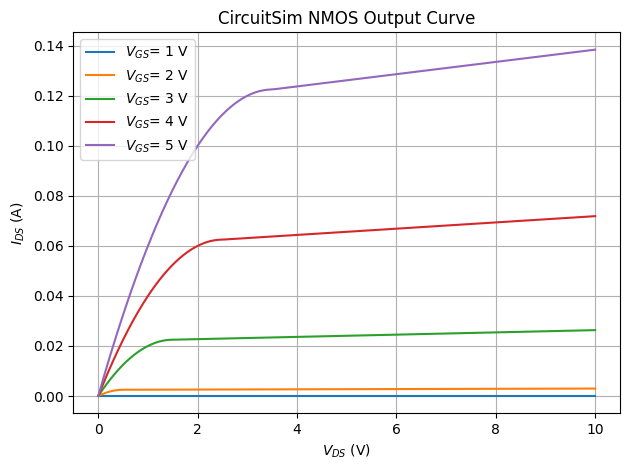
Below is the transfer curve. Its first derivatives are not perfectly smooth, but good enough for our approximations. Looks very similar to the actual curves~
NOT gate
Let’s build a CMOS NOT gate out of this:
void setup(void) {
    vg = 5;
    add_vsrc(1, -1, 3, vg);     // vg
    add_vsrc(0, -1, 4, dc5);    // VDD
    add_nmos(1, 2, -1, 0.02f, 1.5f, 0.01f);
    add_pmos(1, 2, 0, 0.02f, 1.5f, 0.01f);
    nnodes = 5;
}
If you try to use that to build that and try out different vgs, you’ll FAIL miserably. Why?
g_d = 0 in these two regions. The drain node is only connected to current sources. There’s nothing to restrain its value. SINGULAR MATRIX!
I don’t know how Falstad deals with it, but here’s what I did:
- Cutoff: add a small current proportional to \(v_{DS}\)
- The current is smaller than FP accuracy, so it’s typically fine
- Saturation: add channel width modulation term $$(1 + \lambda v_{DS})$ and calculate its derivative
- This term breaks the continuity between linear and saturation significantly. To fix it, we can offset it by a constant
- The better solution is to multiply the same modulation term to the linear term. This will be more elegant
The new partial derivatives need to be calculated appropriately. Calculus moment.
Anyway, here’s the transfer curve. Looks kind of like tanh.
![]()
More gates
With this, you can build any combinatorial (and sequential logic), such as a NAND gate, and even an adder. Here are some helper functions:
void add_not(int vin, int vout, int vDD) {
    add_nmos(vin, vout, -1, 0.02f, 1.5f, 0.01f);
    add_pmos(vin, vout, vDD, 0.02f, 1.5f, 0.01f);
}

void add_nand(int vina, int vinb, int vout, int vn, int vDD) {
    add_nmos(vina, vout, vn, 0.02f, 1.5f, 0.01f);
    add_nmos(vinb, vn, -1, 0.02f, 1.5f, 0.01f);
    add_pmos(vina, vout, vDD, 0.02f, 1.5f, 0.01f);
    add_pmos(vinb, vout, vDD, 0.02f, 1.5f, 0.01f);
}
Write add_xor() for your practice :)