
Applications
Published:
Contents
- Intro to SPICE Algorithm
- Framework and your first circuit!
- More Static Linear Components
- Nonlinear and Diode
- MOSFET
- Time Variance
- Applications (this article)
Now we have all the tools. Let’s build something interesting. I’ll show 3 examples: one analog, one digital, and one mixed.
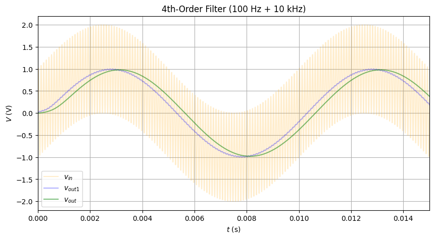
Analog: 4th-Order Filter
I used the Sallen-Key topology (idk a fuck about its details, but it looks like a LPF on the outside!)
float time_step = 5e-6f;
int nsteps = 10000;
int opamp_gain = 1e6f;

void setup(void) {
    // 1) Two‑tone voltage source between node 1 → ground(-1), extra I‑unknown = 0
    add_vsrc(1, -1, 0, two_tone);

    // 2) Stage‑1 Sallen–Key (R1, C1, R2, C2)
    add_res(1, 2, 10000.0f);               // R1 = 10 kΩ
    add_cap(3, -1, 15.915e-9f, time_step); // C1 = 15.915 nF
    add_res(2, 3, 10000.0f);               // R2 = 10 kΩ
    add_cap(2, 4, 15.915e-9f, time_step);  // C2 = 15.915 nF


    add_vcvs(4, -1, 3, 4, 9, 1e6f);         // ideal op‑amp #1

    // 3) Stage‑2 Sallen–Key (identical)
    add_res(4, 5, 10000.0f);               // R3
    add_cap(6, -1, 15.915e-9f, time_step); // C3
    add_res(5, 6, 10000.0f);               // R4
    add_cap(5, 7, 15.915e-9f, time_step);  // C4

    add_vcvs(7, -1, 6, 7, 8, opamp_gain);   // ideal op‑amp #2

    // vout: node 7!
    nnodes = 10;
}
- The corner frequency of this is 1 kHz.
two_toneis implemented by twoSINEsources in series.
Inputting a 100 Hz and 10 kHz combo: perfect filtering
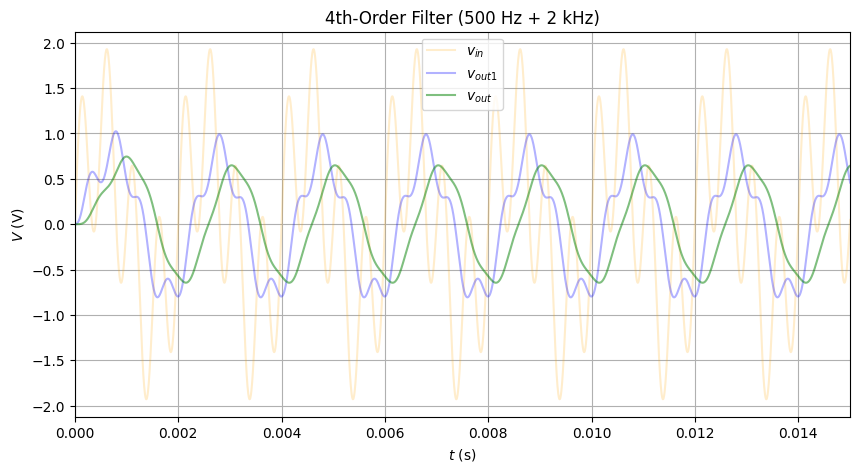
Let’s make it harder, like 500 and 2k, and plot out the result in each stage. Each stage is very accurate, filtering out some components of the 2k while leaving 500 mostly intact. The final output is not perfect, but it’s expected.
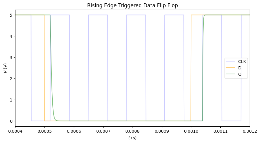
Digital: Rising-Edge Triggered Data Flip Flop
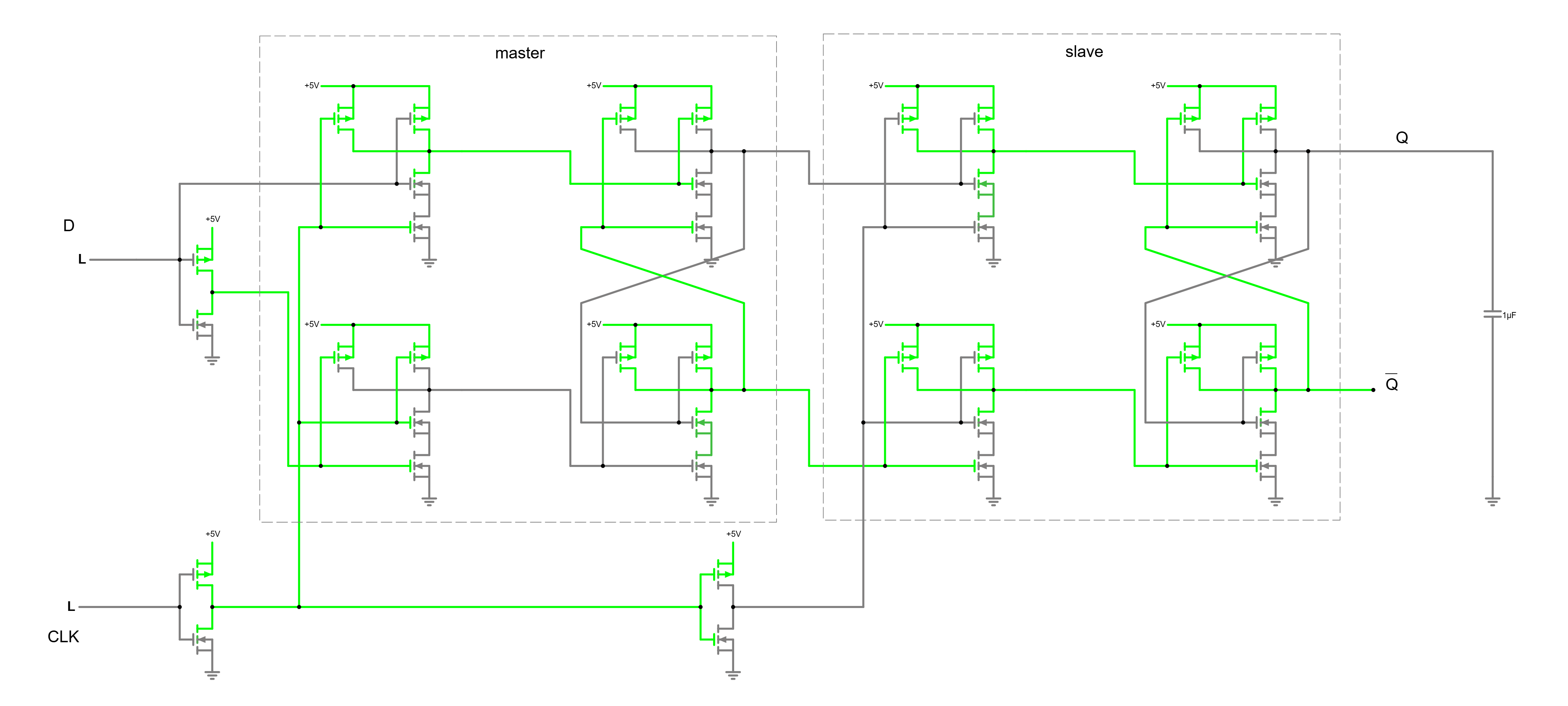
Fundies nightmare! Let’s see if CircuitCim can handle it.
float time_step = 1e-6f;
int nsteps = 10000;

void setup(void) {
    // Node 0, 1: vsrc, vsrc'
    add_vsrc(0, -1, 1, dc5);
    // 2, 3, 4 vin, vin'
    add_vsrc(2, -1, 3, square5);
    add_not(2, 4, 0);
    // 5, 6: CLK
    add_vsrc(5, -1, 6, clk10k);
    // 7, 8: CLK', CLK''
    add_not(5, 7, 0);
    add_not(7, 8, 0);
    // 9-12: master NAND internals
    // 13, 14: master NAND out-
    add_nand(2, 7, 13, 9, 0);
    add_nand(4, 7, 14, 10, 0);
    // 15: 16: master out, out'
    add_nand(13, 16, 15, 11, 0);    // Q master @15
    add_nand(14, 15, 16, 12, 0);

    // 17-20: slave NAND internals
    // 21, 22: slave NAND out-in
    add_nand(15, 8, 21, 17, 0);
    add_nand(16, 8, 22, 18, 0);
    // 23: 24: slave out, out'
    add_nand(21, 24, 23, 19, 0);
    add_nand(22, 23, 24, 20, 0);

    add_cap(23, -1, 1e-7f, time_step);   // output cap
    /* The output cap's charging period must << CLK period. Otherwise it will fail to charge */
    nnodes = 25;
}
There’s nothing too interesting. Just connect the gates appropriately, and pray that CircuitCim handles feedback well. (yes it did)
Exercises:
- There is a more efficient implementation with just 6 NANDs. Implement it
- Match the channel widths to make symmetric rise and fall.
Mixed: 555
Finally, the 555 I promised.
I first looked up a MOS 555 implementation: https://tinyurl.com/2bg6sjrk
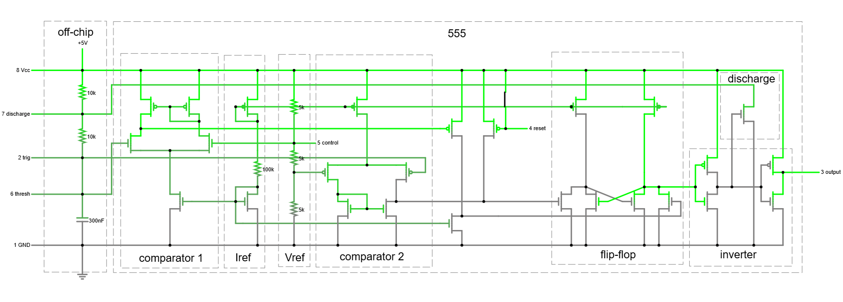
This looked insanely complicated, so I turned it to a “half”-netlist: https://tinyurl.com/26w4885x
- Analog
- Voltage bias for comparators
- Current bias to drive comparators and gates
- Digital
- State holding elements
- Output inverters Doesn’t look too bad now.
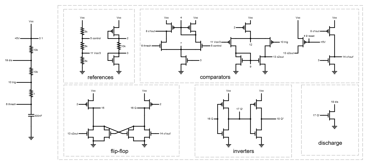
Next is to write out the components. This was a pain, but I made it.
float time_step = 1e-6f;
int nsteps = 10000;

void setup(void) {
    // Node 0, 1: VDD, VDD'
    add_vsrc(0, -1, 1, dc5);

    // 2, 3: current mirror outputs
    add_pmos(2, 2, 0, 0.02f, 1.5f, 0.001f);
    add_nmos(3, 3, -1, 0.02f, 1.5f, 0.001f);
    add_res(2, 3, 1e4f);

    // 4-8: comparator 1
    add_pmos(4, 8, 0, 0.02f, 1.5f, 0.001f);
    add_pmos(4, 4, 0, 0.02f, 1.5f, 0.001f);
    add_nmos(6, 8, 7, 0.02f, 1.5f, 0.001f);
    add_nmos(5, 4, 7, 0.02f, 1.5f, 0.001f);
    add_nmos(3, 7,  -1, 0.02f, 1.5f, 0.001f);

    // 9-13: comparator 2
    add_nmos(9, 9, -1, 0.02f, 1.5f, 0.001f);
    add_nmos(9, 13, -1, 0.02f, 1.5f, 0.001f);
    add_pmos(11, 9, 12, 0.02f, 1.5f, 0.001f);
    add_pmos(10, 13, 12, 0.02f, 1.5f, 0.001f);
    add_pmos(2, 12, 0, 0.02f, 1.5f, 0.001f);

    // 555 voltage divider
    add_res(0, 5, 5e3f);
    add_res(5, 11, 5e3f);
    add_res(11, -1, 5e3f);

    // c1': 14
    add_pmos(8, 14, 0, 0.02f, 1.5f, 0.001f);
    add_nmos(3, 14, -1, 0.02f, 1.5f, 0.001f);

    // 15-16: bistable
    add_pmos(2, 15, 0, 0.02f, 1.5f, 0.001f);
    add_pmos(2, 16, 0, 0.02f, 1.5f, 0.001f);
    add_nmos(13, 15, -1, 0.02f, 1.5f, 0.001f);
    add_nmos(14, 16, -1, 0.02f, 1.5f, 0.001f);
    add_nmos(16, 15, -1, 0.02f, 1.5f, 0.001f);
    add_nmos(15, 16, -1, 0.02f, 1.5f, 0.001f);

    // 17-18: inverters
    add_not(16, 17, 0);
    add_not(17, 18, 0);

    // discharge transistor: 19
    add_nmos(17, 19, -1, 0.02f, 1.5f, 0.001f);

    // off-chip driver
    add_res(0, 19, 1e4f);
    add_res(19, 10, 1e4f);
    add_res(10, 6, 0.01f);
    add_cap(6, -1,3e-8f, time_step);

    nnodes = 20;
}
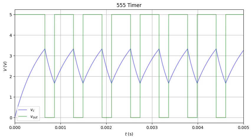
WORKS PERFECTLY in both astable and monostable. There are slight issues on Falstad with the reset function. Have not tested it on CircuitCim yet. If it fails, it’s that the model sucks, and I need to learn more on analog design.
So this completes CircuitCim, the software part of CircuitSim. As I would soon realize, this was only a small part, and the worst suffering was soon to come.
I think the last 555 from scratch really made the “+” part of our grades :)